Parallel Shaft Keys
Notes & Use
Calculates for the selection and design of parallel keys in shafts. Only compressive and shear stresses are taken into account. This calculator does not take into consideration:
- tolerances related to proper fits in a keyway
- localized stresses
- strength of the shaft and/or hub relative to the key material
- abrasion and fatigue resistance
- stresses caused by key rolling or cyclic impact loads
All key depths are assumed to be (0.5 * key height).
The calculator selects a standard key size (height × width) based on the key shape selected, and the shaft size. Note these key sizes per shaft diameter are per ANSI B17.1-1967 (R2003)
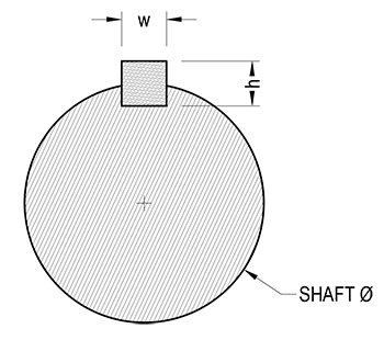
Figure
Terms
$d$ = Shaft diameter, inches
$h$ = key height, inches
$w$ = key width, inches
$l$ = key length, inches
$S$ = Safety factor, unitless
$F_{y}$ = Material yield strength, psi
$T$ = torque thru shaft, in ˙ lbf
$A_{s}$ = Shear area, square inches
$A_{c}$ = Compression area, square inches
$\sigma_{s}$ = Actual shear stress, psi
$\sigma_{c}$ = Actual compression stress, psi
$\tau_{s}$ = Allowable shear stress, psi
$\tau_{c}$ = Actual compression stress, psi
Equations
Shear area: $$ A_{s} = w \times l $$
Compression area: $$ A_{c} = \frac {h \times l} {2} $$
Actual shear stress: $$ \sigma_{s} = \frac {2 T}{d \, l \, w} $$
Actual compressions stress: $$ \sigma_{c} = \frac {4 T}{d \, l \, h} $$
Allowable shear stress: $$ \tau_{s} = \frac {0.5 F_{y}}{S} $$
Allowable compression stress: $$ \tau_{c} = \frac {F_{y}}{S} $$
Pass/Fail Test
$\sigma_{s}$ and $\sigma_{c}$ are compared to the respective allowable values:
- Pass = actual < allowable
- Fail = actual ≥ allowable
Material Yeild Strengths
The design values provided by the drop-down material box are culled from various sources. A full table of those values is as follows:
| Material | $F_{y}$ |
|---|---|
| psi | |
| C1018 Steel | 53,000 |
| C1020 Steel | 51,000 |
| C1045 Steel | 71,000 |
| C1090 Spring Steel | 78,300 |
| A36 Steel | 36,000 |
| 316 SS | 30,000 |
Sources
-
Oberg, Erik, et al., The Machinery’s Handbook, 28th ed., Industrial Press, 2008, pp. 2385.
-
Mott, Robert L. Machine Elements in Mechanical Design, 4th ed., Prentice Hall, 2003, pp. 498-500.